


Give Instrument Status a Permanent Place
A embedded open frame monitor creates value when its task is precisely defined. For laboratory equipment status and procedure guidance, the 13.3-inch unit can present operating state, procedure steps and result summaries from an external instrument computer. The display remains separate from the host, allowing software and computing performance to be selected independently.
The compact widescreen can reserve areas for procedure, current state and result context without mixing display functions with instrument control. The primary user, viewing distance and exception path should be reviewed before content and enclosure approval.
Design Small-Screen Content around Reading Distance
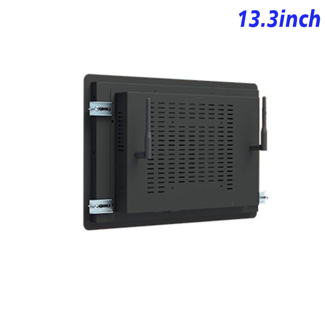
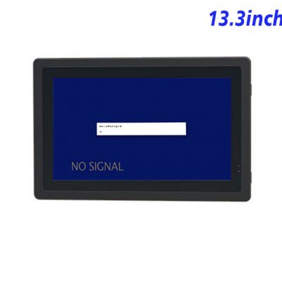
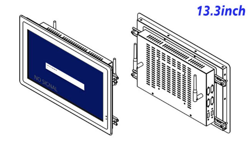
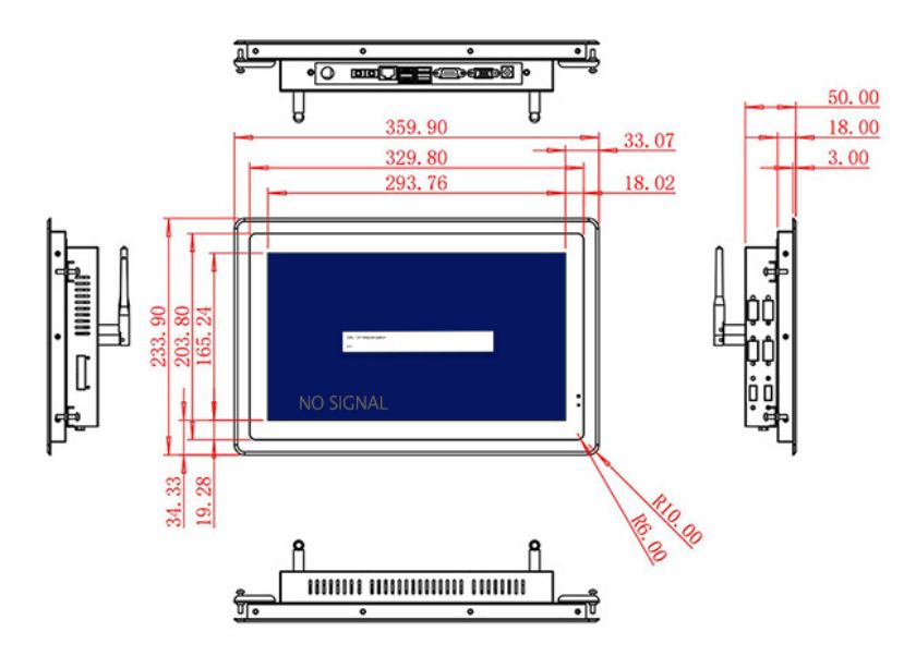
The 13.3-inch LCD is specified with 1920 × 1080 resolution, 220 cd/m² brightness, 800:1 contrast and 85-degree viewing specifications. The system architecture uses external laboratory instrument computer. Maximum power consumption is listed at 25 W, and device dimensions are 359.9 × 233.9 × 50 mm. HDMI, VGA and DVI inputs are listed with USB Type-B for the selected integration. The final configuration and mechanical drawing should be approved together.
Panel figures do not guarantee readability in every fixture. Reflections, font size, color contrast, signal quality and mounting height should be evaluated with realistic content. Any alternative panel or computer option must be named in the approval record.
| External Embedded Display Specifications 13.3 Inch | ||||
| LCD Panel Parameters | Screen Size | 13.3 Inch | ||
| Display Area | 293.76 mm.(Height) X 165.24(Width)mm. | |||
| Aspect Ratio | 16 : 9 | |||
| LCD Type | a-Si TFT-LCD Monitor | |||
| Maximum Resolution | 1920 X 1080 | |||
| Display Color | 262K, 45% NTSC | |||
| Brightness | 220cd/m² | |||
| Contrast Ratio | 800 : 1 | |||
| Viewing Angle (Up/Down/Left/Right) | 85°/85°/85°/85° (Type)(CR≥10) | |||
| Response Time | 30ms | |||
| LCD Panel Lifespan (Hours) | 60,000(Hour.) | |||
| Field Frequency | 60Hertz | |||
| Audio Parameters (External Speaker Option) |
Audio system | Stereo | ||
| Speaker size | ≈ 99 x 45 x 20 mm | |||
| Impedance | 8 Ohm | |||
| Power | 2 x 5 Watt | |||
| Loudness | > 80 Decibel | |||
| Interface | 4-pin connector | |||
| Onboard Interface | HDMI Input | 1 | ||
| VGA Input | 1 | |||
| DVI Input | 1 | |||
| USB Type B or any desired USB Type | 1 | |||
| Power | Power Supply | Alternating Current 100V~240V, 50/60Hz | ||
| Maximum Power Loss | ≤ 25 Watt | |||
| Standby Mode Power Loss | < 1 Watt | |||
| Features | Operating Temperature | 0℃ ~ 50℃ | ||
| Storage Temperature | Below 10℃ ~ +60℃ | |||
| Package Size | Device Dimensions | 359.9 X 233.9 X 50 mm. | ||
| Net Weight | 3 Kilogram | |||
| Package Size | 42 X 29 X 15Centimeter | |||
| Gross Package Weight per Unit | 4 Kilogram | |||
Connect to the Validated Instrument Host
Video Signal
The external host owns software, networking, storage and recovery. Its output resolution, startup order and cable path should be tested with the selected input. Clear ownership prevents a blank or frozen page from automatically being blamed on the display.
Instrument Responsibility
The display is not calibrated measurement equipment, and the table does not confirm sealing, serial control or touch. Measurement authority remains with validated instruments and software. The title, specification table, marketing copy and final bill of materials must describe the same capability.
Keep Measurement and Display Roles Distinct
Mechanical Integration
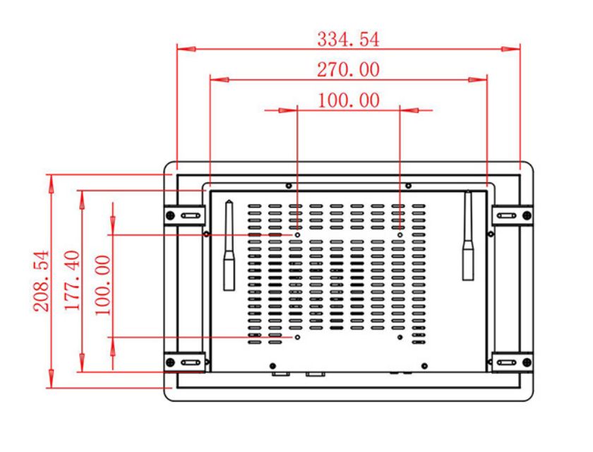
The integration drawing should identify front opening, mounting points, rear depth, ventilation, power route, cable bend radius and removal clearance. Connectors need to remain accessible after the host cabinet is assembled.
Recovery testing should include power interruption, missing video or network, invalid input and application restart. Diagnosing one layer at a time helps determine whether a problem belongs to display hardware, computing, cable, software or connected equipment.
Use Fault and Calibration Messages in the Pilot
The first embedded open frame monitor should be tested with representative normal and fault conditions. Teams can record reading errors, task time, operator questions, recovery steps and service access before releasing multiple units.
An engineering sample also verifies appearance, connector position, signal compatibility and boot behavior. These details cannot be confirmed from product photographs, especially when another supplier fabricates the surrounding enclosure.
ZXTLCD can review the application, host or computing configuration, mounting drawing, interfaces, quantity and installation conditions before production. For repeat embedded open frame monitor projects, the approved sample and configuration record help integrators keep panel, electronics, connectors and mechanical details consistent across later deliveries. The review should include the intended signal source, cable length, startup sequence, installation orientation and access available to a service technician. Recording these details gives purchasing, engineering and after-sales teams the same reference when a future batch or replacement unit is requested. It also reduces last-minute changes after the surrounding cabinet has already entered production.
Repeat orders should reference the approved panel, electronics, interfaces, power specification, software or host signal and mechanical drawing. This documentation supports phased installation and future replacement without repeating the original integration decisions.
If you would like to get the specification about above product, or you hope to discuss your requirements or need any additional information on our this product, then please do not hesitate to send us a inquiry and contact our sales team now.
Request Product Information
If you would like to get the specification about above product, or you hope to discuss your requirements or need any additional information on our this product , then please do not hesitate to send us a inquiry and contact our sales team now.