

Keep Instrument Prompts close to the Operator
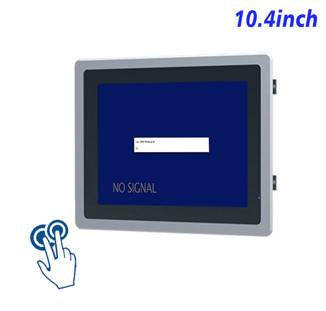
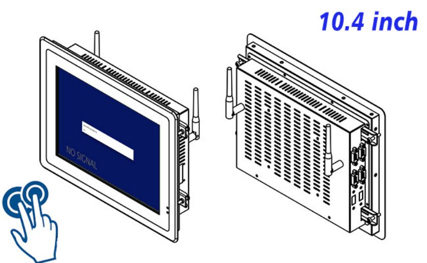
The available opening, user task and software load should define the hardware choice. For indoor diagnostic equipment and laboratory workstations, this 10.4-inch medical equipment touch display can present instrument menus, status fields and operator prompts from a separate medical computer. Its value comes from supporting compact 4:3 interaction beside specialized equipment, not from adding unrelated kiosk claims.
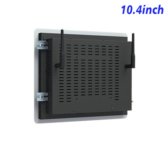
The LCD, capacitive touch layer and input electronics form one display assembly, while computing remains in the external host. This distinction prevents buyers from expecting an operating system or application inside the monitor. The project still needs approved wiring, airflow, mounting clearances and peripheral ownership. Screen layout should be tested at the real viewing distance with the people who will use it.
Use a Compact Screen for Focused Tasks
| ZXTLCD-EW104BCTS 10.4-inch External Embedded Capacitive Touchscreen Display Specification Document | ||||
| LCD Panel Parameters | Screen Size | 10.4 Inch | ||
| Display Area | 211.2 mm.(Height) X 158.4(Width)mm. | |||
| Aspect Ratio | 16 : 9 | |||
| LCD Type | a-Si TFT-LCD Monitor | |||
| Maximum Resolution | 800 X 600 | |||
| Display Color | 16.7M | |||
| Brightness | 400cd/m² | |||
| Contrast Ratio | 700 : 1 | |||
| Viewing Angle (Up/Down/Left/Right) | 80°/80°/70°/70° (Type)(CR≥10) | |||
| Response Time | 30ms | |||
| LCD Panel Lifespan (Hours) | 60,000(Hour.) | |||
| Field Frequency | 60Hertz | |||
| PCAP Touchscreen Panel Parameters | Touch Pattern | Capacitive Touchscreen Capacitive Projected | ||
| Touch Points | 10 Points | |||
| Cover Glass | Morse Glass Size 7 Physically reinforced to prevent explosion | |||
| Glass 3 mm. Optical mount to reduce parallax | ||||
| Glass Transmission | >85% (Higher light transmission depends on glass coating technology For example AR/AG) >85% | |||
| Response Speed | < 6ms | |||
| Touch Accuracy | More than 90% of the touch area ±2 mm | |||
| Touch Method | Inch Stylus | |||
| Output Format | Coordinate Output | |||
| Click Time | Unlimited | |||
| Smallest Touch Size | 5 mm | |||
| Long-lasting Durability | Yes, Available | |||
| Touch Interface | USB | |||
| Operating Temperature and Humidity | Below 10℃ ~ +50℃, ≤ 85%RH | |||
| Storage Temperature and Humidity | Less than 20℃ ~ +60℃, ≤ 90%RH | |||
| Audio Parameters (External Speaker Option) |
Audio system | Stereo | ||
| Speaker size | ≈ 99 x 45 x 20 mm | |||
| Impedance | 8 Ohm | |||
| Power | 2 x 5 Watt | |||
| Loudness | > 80 Decibel | |||
| Interface | 4-pin connector | |||
| Onboard Interface | HDMI Input | 1 | ||
| VGA Input | 1 | |||
| DVI Input | 1 | |||
| USB Type B or any desired USB Type | 1 | |||
| Power | Power Supply | Alternating Current 100V~240V, 50/60Hz | ||
| Maximum Power Loss | ≤ 15 Watt | |||
| Standby Mode Power Loss | < 1 Watt | |||
| Features | Operating Temperature | 0℃ ~ 50℃ | ||
| Storage Temperature | Below 10℃ ~ +60℃ | |||
| Accessories | Power Cord Length | 1.5m | ||
| HDMI Cable Length | 2m | |||
| USB-A to USB-B Cable Length | 1.5m | |||
| Stereo Speaker Size with Connector | 99*45*20mm | |||
| Stereo Speaker Length | 1.5m | |||
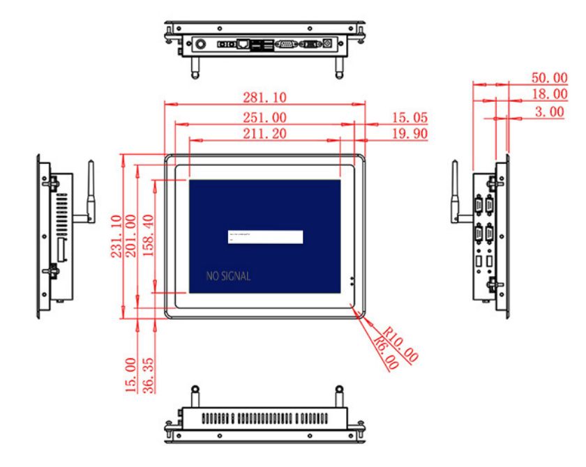
| Package Size | Device Dimensions | 281.1 X 231.1 X 50 mm. | ||
| Net Weight | 2 Kilogram | |||
| Package Size | 33.5 X 18.5 X 15 Centimeter | |||
| Gross Package Weight per Unit | 2.5 Kilogram | |||
Medical host
The documented 10.4-inch LCD provides 800 × 600 resolution, 400 cd/m² brightness and 700:1 contrast. It uses a 10-point projected-capacitive touch layer with USB interface, 3 mm strengthened cover glass, more than 85% transmission, less than 6 ms response and stated touch accuracy. The display requires an external medical computer supplied and validated separately. Available connections include HDMI, VGA and DVI video inputs plus USB touch connection. Maximum power consumption is 15 W, while the listed device dimensions are 281.1 × 231.1 × 50 mm. These values must remain tied to the approved configuration because options shown in the same table are not automatically combined.
The numbers describe the base hardware rather than a finished business system. Application performance depends on the external computer, graphics output, USB touch mapping, software and connected equipment. Video input and USB touch should be documented as separate paths. Procurement documents should repeat the approved option set instead of copying every alternative from the specification table.
Match the Display to the Medical Host
Instrument boundary
A stable installation begins by matching the host resolution and video output to the display, then connecting USB for touch coordinates. The team should test startup order, signal loss, sleep and wake behavior, touch alignment and recovery after the host restarts. Open administrator access and undocumented changes create avoidable support work.
Fixture access
Clinical decisions, instrument control, electrical compliance and patient data are not functions of the display. Product title, sales copy, drawings, software scope and bill of materials should describe the same finished capability. This protects both the buyer and integrator from assuming that an application, certification or peripheral is included when it is not.
Separate Clinical Functions from Touch Input
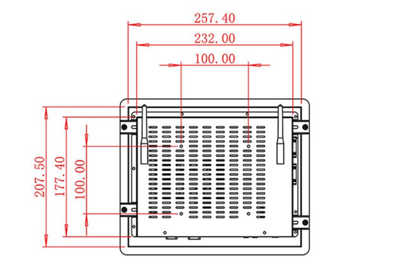
Mechanical integration drawings should identify the front opening, fixing points, rear depth, ventilation path, power route, video and USB routes, connector access and removal clearance. A scanner, printer, reader, camera or payment module should be documented and serviced independently instead of becoming inaccessible behind the panel.
Touch interaction also needs realistic testing. Long labels, multilingual content, invalid entries, unavailable records and interrupted connections reveal more than a perfect demonstration. Buttons, warning states and confirmation steps should remain readable without requiring users to understand the internal system.
Validate Cleaning and Signal Recovery
Touch mapping
The first medical equipment touch display should be treated as an engineering sample. Acceptance can record signal acquisition, native resolution, USB touch alignment, sleep recovery and cable retention. The team should also confirm that no product model appears in customer-facing marketing text.
A representative workflow should run from the opening screen to the final confirmation or exception. Measure task time, repeated actions, staff assistance and recovery steps. Findings can be corrected in the host software and cable plan or fixture before volume production, when changes remain inexpensive.
ZXTLCD can review the screen option, host output and touch connection, workflow, mounting drawing, peripherals, quantity and operating conditions before production. For repeat medical equipment touch display projects, the approved sample record helps purchasing, engineering and after-sales teams keep the panel, touch layer, input board and cables, connectors and mechanics consistent.
Handover records should include the host resolution, video input and USB touch mapping, connector map, drawing revision and replacement procedure. This gives future batches and spare units a practical reference without turning the product page into a promise of unsupported functions.
Request Product Information
If you would like to get the specification about above product, or you hope to discuss your requirements or need any additional information on our this product , then please do not hesitate to send us a inquiry and contact our sales team now.